

| 
| 
| 
| 
| 
| 
| 
|
 wersja polska)
|
The facts about Cygnus-2 - an unmanned stratospheric balloon:
|
When i was a young child, I released a couple of toy balloons and watched
them gracefully disappear over the bay. My first thought was to strap some
electronics, a TV camera and a radio transmitter to them and do a survey of
the coast. I realized that would be beyond the budget and technical
skills of a youngster, but the idea stayed in my mind. Ever since I was
always interested when someone sent something up. :-)
A few months ago (as of June 2006), when I was searching the web for some ham
radio related stuff, I came across a site of a US based high altitude
ballooning group. I knew this was it! A meteorological balloon was the way
to go. After a multitude of sleepless nights
and hauling a few hundred kilograms of helium tanks - success! Read on...
 The flight system consists of a latex meteorological atmosphere
sounding balloon, designed to burst at a particular altitude,
a woven nylon load line connected to the parachute,
and the payload - an environmentally rugged case containing avionics,
communication systems, cameras and experiments.
High altitude (also called Near Space - somewhat boastfully, as the
altitudes reached are halfway into space :-) conditions
are quite forbidding and demands placed at the flight system, especially the
avionics, are high. Temperature spans from +30°C on the ground to
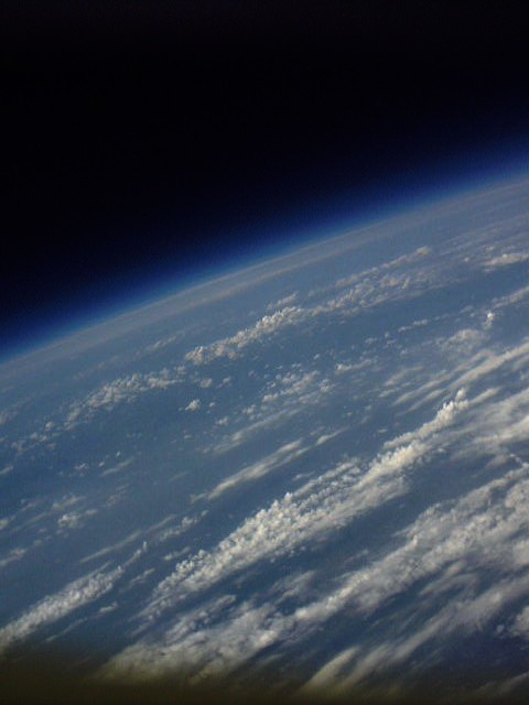
-60°C at 30km, air pressure is nearly zero, the sky is completely black
and you can see Earth's curvature.
The whole payload spins and
swings, especially after the balloon bursts. The landing can be hard if the
shroud lines get coiled or if the flight recovers on a cement sidewalk.
Everything has to be robust and light at the same time, as weight costs
altitude - not to mention the regulations, which are pretty strict.
I had to decide what i wanted the balloon to do. Now, there are lots of things
people put in payloads, like cameras, ham radio repeaters, geiger counters,
etc. For the first flight I focused on successful launch, tracking and
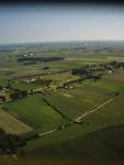
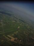
recovery, with photos being a bonus and an eye-candy.
| 
| 
|
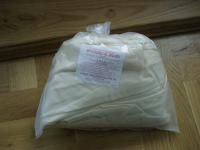
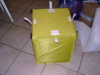
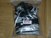
| Balloon | Payload container | Parachute |
I called the Insytut Meteorologii i Gospodarki Wodnej
(Institute of Meteorology and Water Management) - the Polish National Weather Service
and asked them where they get their balloons. I was redirected to the
Department of Aerology in Legionowo where I was told they get balloons
either from Kaymont or from another manufacturer in Japan. As the cost of
shipment from Japan would be overkill, I decided to order from
Kaymont. I got a 1500g sounding balloon,
the KCI1500
for $90.
The parachute is a $46 R7C standard 8lbs rocketry chute from
The Rocketman Store.
The choice of the load line seemed a bit problematic - for air traffic safety
reasons, the regulations require the line to break under no more than 230N of
force, but the kind of force is unspecified. It is not tensile force,
because a line that'd break under 230N of tensile force would snap during
launch. Luckily, information on EOSS
site cleared up the issue. I used a woven nylon cord and a sisal cord loop
to tie the load line to the balloon (sisal cord is not slippy and nylon cord
is) - every knot was secured with quality
duct tape (yes! yes! I'm a fan of duct taping everything, as long as it's
real duct tape and not a poor excuse for one). The nylon cord is tied to a
loop at the top of the parachute and the parachute is connected to the
payload - this way the chute doesn't have to be released in any way,
it just stays there unfolded and waits for the balloon to burst. :-)
Current (as of June 2006) regulations pertaining to unmanned free balloons
in Poland can be found in "Dz. U. nr 414/2004". In short: as long as the payload doesn't exceed
3kg (6.5 lbs), its density doesn't exceed 13g/sq. cm and the load line breaks under no
more than 230N of strength, and you get a permission - you're OK. It took me
a few days to sort out all the details, as they kept redirecting me from one
agency to another. Eventually I found out that the
Agencja Ruchu Lotniczego -
Air Traffic Agency is responsible for processing permission requests.
Thanks to a very helpful person there, I got my permission in a week.
They also publish a NOTAM (Notice to Airmen) to warn pilots of an upcoming balloon
flight.
I needed the avionics to be as lightweight and robust as possible. I had the
choice between picking a commercialy available low-power device, or
designing one on my own. As the project was supposed to be fun, :-) I chose
the latter.
I've designed the Cygnus flight computer and avionics to be microprocessor-based,
highly specialized interchangeable modules, communicating by slow speed serial
interfaces. The microprocessor architecture of choice is Atmel 8bit AVR RISC. The
AVRs have lots of built-in features making them (in my opinion :-)
superior to PICs or similar devices. They also have proven themselves robust
enough to withstand harsh environmental conditions and RF interference.
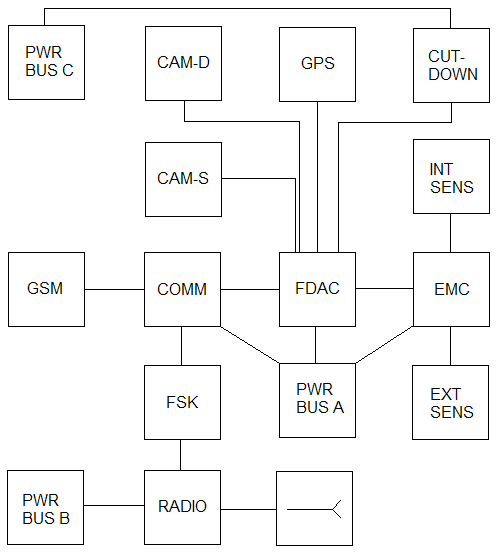 The avionics core consists of three main computers:
The FDAC contains main flight logic. It manages other modules, makes
control decisions based on external/internal data and triggers execution
of on-board experiments. FDAC works in real-time. It has "ears" - the GPS
module, the COMM module and the EMC module, "eyes" - the down-looking and
side-looking cameras and a "knife hand" - an emergency balloon cutdown
device. The FDAC also controls a 80dB piezo buzzer and an ultra-bright LED
beacon for optional night time recoveries.
The COMM module manages communication with the balloon. There are two
systems for that: a custom-built FSK (Frequency Shift Keying modulation)
modem module (based on the CML Microcircuits FX614
FSK modulator-demodulator chip) for transmitting custom-format ASCII
telemetry and receiving commands; this design allows use of any radio TRX
with an audio (mike) input and remote keying - from 2m amateur handheld
transceivers to compact ISM band embedded radio modules, and a wide choice
of antennas - j-poles, dipoles and even good quality rubber duckies, if
there is such a thing. :-) I chose to go with a twin-lead j-pole, since it's
easy to make, and what's important, flexible - it doesn't need a support
structure.
The second system is a GSM phone. There's very good network
coverage in Poland, even in remote rural areas. GSM is not designed for air
telephony and no base stations' sector and omni-directional antennas are
"aimed" at the sky. When the balloon ascends, it "sees" the horizon farther
away, so communication becomes possible with distant GSM base stations,
however real-life tests showed there is absolutely no GSM reception above
650m (2100ft). So it's not like in the movies! Knowing that, the GSM phone
still is a useful recovery aid -- sending the landing site position via SMS
messages. I used a Nokia 6310 phone -- it's old enough to have a pretty good
RF section (though not as good as the 6110) and modern enough to use
Hayes AT commands and not Nokia's proprietary FBUS protocol (which is a
reall hell to program -- it took me 15+ hours to do SMS sending with FBUS,
while with AT commands connecting the cable took longer than programming
:-). I used a Nokia DLR-3P standard serial cable to connect it to COMM
module's hardware UART.
The COMM module communicates with FDAC using a 300bps serial interface.
The EMC module is responsible for sampling and formatting environmental data
from internal and external sensors: external temperature, external absolute
air pressure, internal temperature, main battery pack temperature, radio
temperature. I used Dallas (now Dallas/Maxim) DS18B20 series digital temperature sensors and
a Motorola MPX series absolute pressure sensor.
The Honeywell relative humidity sensor didn't make it in
time, so it didn't fly.
The EMC module communicates with FDAC using a 1200bps serial interface.
| 
| 
|
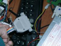
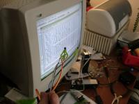
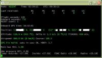
| External sensors -- sealed with hot glue in a DB25 case | Internal sensors | Ground station telemetry software |
The emergency cutdown device is mounted on top of the parachute. It is a
piece of NiCr (nichrome) wire tightly wound around the load line and
connected to screw terminals on the PCB. Power to the wire is switched by
a 10 amp MOSFET and controlled by the FDAC.
The wire gets glowing hot in less than a second and melts the nylon load
line, separating the balloon from the parachute and initiating descent.
Due to high-amp loads placed by the wire, the cutdown circuit has its own
small battery pack.
There are two reasons to actually use the cutdown: if the balloon becomes
neutrally buoyant (i.e. won't ascend high enough to burst) and it stays in
the air long enough to pose a threat for air traffic at night - I read it
happens sometimes - rarely. The second reason is a "runaway balloon" - if it
becomes obvious the balloon will travel too far from the launch site for
recovery to be feasible, or will land in an inaccessible place like a swamp.
I needed to know where the balloon was to record its altitude (a pressure
based altimeter is not an option due to inability to calibrate it properly
in an amateur lab and too low pressure at near space altitudes; a radar
based altimeter is beyond amateur budget and it's too heavy) and to recover
it after landing. The choice was obvious: a GPS receiver.
After thorough research I decided on a $180
Garmin GPS-35 trackpack.
It's not the best one around sensitivity-wise, as it's based on an old Garmin chip - no
match for modern Sirf Star III receivers. It is, however, environmentally
rugged, it's a complete package (receiver and antenna in one case - hence
the name "trackpack"), and it's been successfully used by ballooning groups
all over the world. It's also known not to have altitude restrictions as
some commercial GPSes do. I chose a GPS-35LVS submodel. It's designed for a low
voltage supply (3.6V to 6V) and outputs RS-232 levels on its two serial ports.
I supplied the GPS with 5V from Power Bus A and connected the first serial port
(ASCII NMEA output, 4800 baud) to FDAC's hardware UART.
The cameras for the first flight had to have one feature: low cost. ;-) Really,
for a test flight, which I didn't even know if i was able to recover, there
was no sense in using expensive multimegapixel devices. I needed two
features: a way to rig the shutter pushbutton to flight computer's
output and a possibility of disabling the automatic poweroff, so happily
included by camera manufacturers these days. :-)
Again, some heavy research was in order. I found
Aiptek PenCam 1.3 Mega and got two
here for $30 each - not a
bargain, if you ask me. ;-) These cameras are in fact just toys, I wouldn't even use
them to take a photo for the family album. They claim to have a 1.3Mpix
sensor, but color quality, flaring and JPEG compression artifacts make it
impossible to use the "high quality" mode. I settled for VGA (640x480) low
quality mode. The cameras have 16MB of built-in flash, enough for about 190
pictures in VGA mode. They're normally powered by two AA batteries,
but there's a really nice feature available: power by USB. In USB power
mode, you don't have to have batteries in the tray, the on/off switch is
inactive (so there's no worry about accidentaly switching it off) and what's
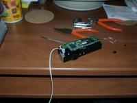
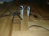
most important, the auto poweroff is disabled. I bought an additional USB
cable (for downloading pictures), cannibalized two cables that came with
the cameras and connected them to 5V Power Bus A. Then, thanks to my wife
(who can open pretty much everything without destroying it :-) we opened the
made-in-Taiwan-plastic cases and I replaced the original shutter pushbutton
with a cable. A quick test confirmed that a NPN transistor can switch the
shutter. There was one more button to deal with, the mode button. I didn't
want to mess with it because it was SMD and besides, I thought I might need
to use it manually so I left it as it was. The cameras are unable to
remember the mode they were in before poweroff, so they have to be switched
to low quality mode every time.
| 
| 
|
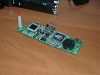
| PenCam 1.3 PCB shutter pushbutton removed | Remote shutter cable | Cameras ready to be installed |
Taking into consideration the harsh operating environment, the only feasible
power source are primary (non-rechargable) lithium cells. Not to be mistaken
with rechargable Lithium-Ion or Lithium-Polymer batteries, lithiums are
capable of operating under low or high temperatures and sourcing higher
current than any commercialy available cells. Lithium cells come in two
flavours. There are military surplus battery packs containing 3V
lithium-manganese dioxide chemistry cells (Li/Mn O2) and consumer AA/AAA
size 1.5V lithium-iron disulfide (Li/Fe S2) cells. As military surplus
lithiums would probably be very hard to come by in Poland, I settled for
Energizer L91
AA size batteries. I got them from
here, they
come in packs of two for under $6.
They are rated for operating temperatures from -40 to
60°C, 3000mAh capacity and 2 amps continuous drain. They're also much
lighter than alkaline cells, weighing only 14.5 grams! I arranged them into
battery packs of six -- giving 9V, one for each of the power buses.
The battery holders I ordered turned out to be of very poor quality - made
of soft plastic and with tiny springs as negative terminals so even duct
taping the batteries didn't do any good - one bump and there'd be a power
loss. This was, of course, unacceptable. Fortunately I devised a clever
makeshift way to fix the problem by putting flattened BNC connector sleeves
against positive terminals, flooding the whole battery pack with hot glue and
finally sealing it with duct tape. Talk about improvising!
Power Bus A needed 5V, so I used a low dropout, 1A step-down converter,
National
Semiconductor LM2940. With a standard TO220 heatsink, it also served as
a heater for the payload, generating about 50-60°C. Power Bus A draws
exactly 500mA (including the cameras and GPS).
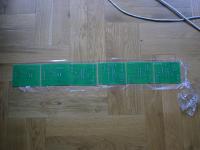
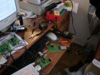
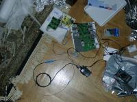
Most of the electronics consisted of 10x8cm modules, secured with wire ties
to sheets of plastic with neoprene foam as cushion. The connectors of choice
were male DB9 sockets and female DB9 plugs (they are sometimes used in
satellite avionics - with metal casings). I couldn't afford the added weight,
so I used plastic casings. All electronic parts are industrial
versions, certified to work below 0°C. I get parts from
here.
| 
| 
|
| Fresh PCBs, straight from the PCB house :-) | Building&testing avionics | Part of the avionics on test pallets |
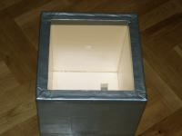
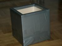
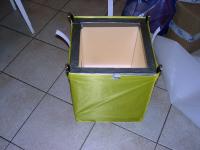
I built the payload container to be reusable and sturdy. Its main purpose
is keeping the avionics warm under extreme cold at high altitudes.
The walls are made of styrofoam. Now, I learned that the real Styrofoam is
NOT your regular packing-grade white styrofoam. It is extruded polystyrene
(XPS), used for building insulation. I found the original Dow Styrofoam to
be very expensive, fortunately there are counterparts, like the
Ursa
XPS. I got three square meters of 3cm thick XPS
here
for about $15. The walls were carefully cut and hot glued together by
my wife. The capsule is NOT airtight and it shouldn't be.
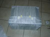
I wrapped the container in additional insulation, consisting of
multiple layers of space blanket separated by nylon curtain fabric, allowing
the heat generated by the payload to be reflected back inside. Most of the
ballooning groups use space blankets made of aluminized mylar (NRC foil).
Aluminized mylar used as payload insulation has one downside: it blocks
radio reception, requiring either external GPS and GSM antennas or leaving
the hatch uninsulated. I was lucky to get a non-aluminized space blanket
(foil), which worked just as good, but allowed me to leave the GPS inside and
use the phone's built-in antenna. Borrowing a design from
KNSP, I
(again with the help of my irreplaceable wife - actually she did most of it :-)
made a thin rip-stop nylon (sail cloth) jacket for the container. The jacket
protects the space blanket insulation and secures the hatch to the box
with Velcro straps. It also serves as support for the payload and parachute
attachment point (four nylon straps with metal key rings are sewn into the
rip-stop at the corners) A 5cm (2 inch) thick rubber foam shock absorber
is glued to the bottom of the container, to ensure a soft landing.
Tests revealed that thanks to the rubber foam, the capsule always recovers
on its side.
| 
| 
| 
|
| Payload container insulation | Container interior | Container exterior | Without the hatch |
There are two choices of gas: helium and hydrogen. Professionals use
hydrogen as it's much cheaper. Unfortunately, it's also extremely flammable
and explosive. Balloons and hydrogen don't go well together - you know what
I mean if you heard about the Hindenburg disaster.
I got helium from Linde
Gaz, two 5.6m3 (200 cu. ft) tanks (alas, they were out of
7m3 tanks) for $100 each. Using equations from the
helium calculations
spreadsheet by macfreak, I prepared a tiny but useful GNU bc
script for calculating the amount of helium needed.
Filling the balloon in the field confirmed the calculations were correct.
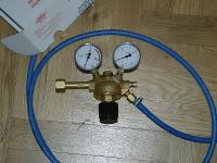
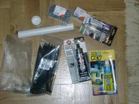
I made a filler similar to the ones used by meteorologists - an industrial
helium regulator I bought here for $50
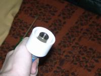
and attached to it a 3 meter (10 ft) oxygen hose. On the business end,
there's a 1 inch PVC cap with a hole drilled in the center. The hose has a
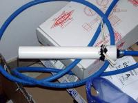
barb at the end, and the barb is held in the PVC cap by a bushing. A 30cm
length of 1 inch PVC pipe is glued with PVC glue to the PVC cap (the pipe is
inserted into balloon nozzle for filling). A sisal cord
loop is attached to the PVC pipe for weighing the balloon lift force during filling
(with a 5kg spring scale, available at fishing stores). Everything is
secured with black silicone (RTV).
| 
| 
| 
|
| Helium regulator | PVC cap | Filler nozzle | Various adhesives and misc. stuff |
It'd be most convenient to launch from Warsaw, or some place near the city.
That, however, was not an option as the balloon would certainly pose a
threat to air traffic and the payload could land on top of a skyscraper.
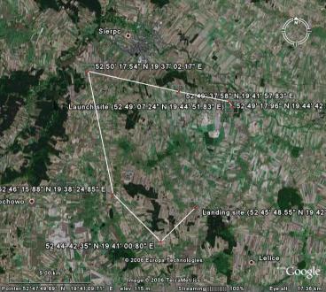
I decided on a 150km (95 mile) radius around Warsaw. After going through
the maps, ruling out swamps, forests, densely populated areas, etc. I chose
a village called Dziembakowo near the town Sierpc. It's a rural area
with vast plains and a few small forests. I got the permission a fortnight
before the launch date, which was set for June 20th (2006). Three days
before the launch we got the helium and final payload systems tests were
conducted. Unfortunately, the tests revealed a problem with the radio -
probably a burnt final stage transistor. As there was no more time for
diagnostics and repairs, I decided to rely on the backup GSM phone. In the
evening before the launch we packed everything into the car. The final
plugs-out test of the payload confirmed it was working fine; battery
packs were sealed and secured inside.
We didn't get much sleep (not that I could sleep anyway) and left at 05:30.
The traffic at this inhuman (for me) hour was light, so we left Warsaw
behind quickly and got on the highway. It was a two hour drive to the launch
site, pretty pleasant if not for the helium tanks, which are so tall they
didn't fit horizontally into the trunk of the sedan, we had to lay the
back seat down and I sat on top of the bent seat, bumping my head against
the roof a few hundred times. ;-)
When we got there, we were ahead of schedule (it was 08:00 and the launch
time in the permission was set for 11:00). At 10:00 I called Warsaw
Area Control, confirmed the launch time and we started preparations.
I weighed the flight system (payload, load line and parachute), added the
balloon weight and three pounds (1.36kg) of lift (I wanted the balloon to go as fast
upwards as possible), powered up the payload avionics and let them run to warm up
and to confirm their operation. We hauled the tanks out of the car, prepared the filler and rolled out
the balloon on bed sheets, to protect the latex envelope from sharp plants
and glass (there was broken glass on the ground as it was probably a local
drinking company's picnic place :-). Twenty minutes before the launch we
started to fill the balloon. I expected some trouble with that, but there
was none. It went flawlessly. Once the balloon got off the ground,
we started measuring lift force. I had to switch tanks for the final few
hundred grams of lift. I decided to go with two pounds of lift, instead of
three, so I stopped adding helium and sealed the balloon nozzle. I was
holding the nozzle (not an easy task to hold a balloon two meters in
diameter, generating 5kg of lift) while my wife connected the load line to
the balloon, the parachute to the load line, and the payload to the
parachute. We saw in horror that the load line was a little frayed in one
place, but there was nothing we could do with it. I verified flight computer
operation and GPS position fix and began to let go, first the balloon,
then the parachute and finally the payload (I got string burns despite wearing
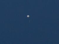
gloves). It went up much faster than I anticipated. I called ACC Warsaw
again, confirmed balloon release and gave them the ascent rate. I received
the last SMS from 650m (2100ft), as it was expected. All systems were
working just fine. After a while of watching the balloon ascend, we packed
everything into the car and decided to find a place in the shade, as it was
noon and we started to feel like eggs on a frying pan. :-)
Then, after a little more than an hour and a half, I received the first SMS
from the payload! All systems were still nominal, there was a solid GPS fix
with as much as 10 useable satellites and the altitude of 127m AMSL confirmed
that the payload has landed. I quickly put up a map on my PDA and entered
the coordinates. We were surprised the payload landed only 6.5km (4 miles)
from the launch site. We drove there as fast as traffic law allowed :-)
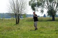
(fearing someone could steal the payload), got out of the car and since the
payload was nowhere to be seen, I switched to navigation software on the PDA
(I use BeeLineGPS)
and we started to line up the latitude. It seemed that the payload landed on
the field, so we entered it and started our little cross-country survival. ;-)
There were raspberries and nettles all over the place, so we got badly
scratched (and, as it turned out later, even more badly sunburned). Every
time we thought we were near the payload I called the phone to trigger the
piezo buzzer, but we didn't hear anything. We decided to take the
mathematical approach and precisely lined up the latitude and longitude.
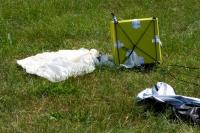
There it was! Lying on its side just about 15-20 meters from the GPS
reported position. The balloon remains were still attached to the load line,
and they were curled so tightly in one place, I thought I accidentally
picked up a rock with the balloon envelope. We returned to the car,
downloaded the pictures from both cameras and flight computer data to my
laptop and shut down payload systems. Visual inspection of the payload showed
no damage at all, not a scratch. Mission successful! It was time to head
for home.
| 
| 
|
| Cygnus-2 ascending | There it is! Found the landing site | Landing site |